Installing The Chassis
This tutorial will provide a step-by-step walk through of the processes, tips, and techniques used to install our custom bagged style chassis under Greenlight 1967-1972 C-10 long bed tucks.
Recommended Tools:
#55 Drill Bit
0-80 Tap
0-80 Flat Head Screws
6” Machinist’s Ruler (w/ 64ths)
Jeweler’s Saw
3/0 Saw Blades
Exacto Knife
Fine Point Marker
Dremel Rotary Tool
Two Sets of Pliers
1/16” & 1/8” Carving/Engraving Burr
Painter’s Tape
Assorted Files

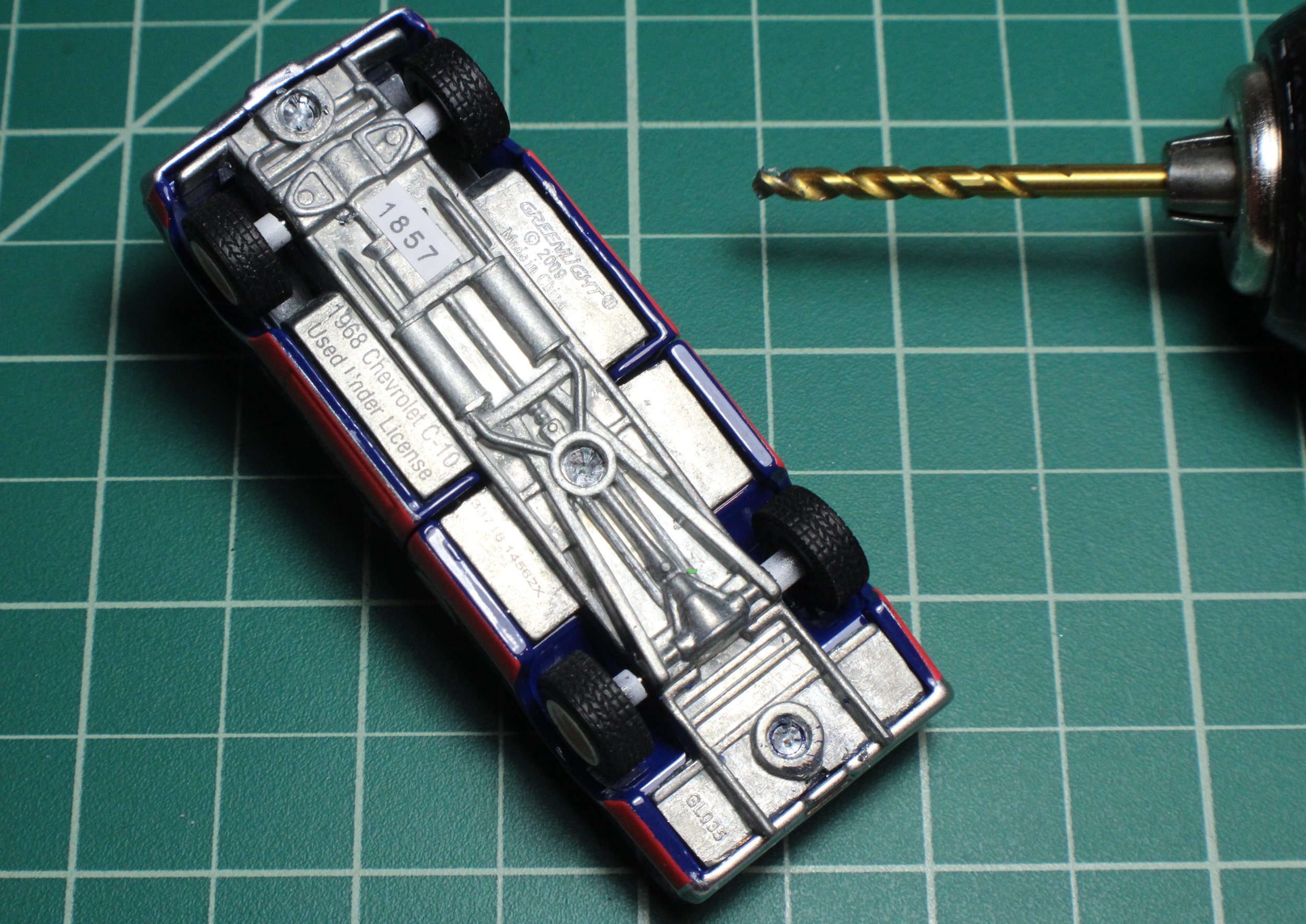
The truck used in this tutorial is a 1968 Chevrolet long bed truck. These steps will apply for any 1967-1972 long bed C-10 truck made by Greenlight.

1. The three rivets that hold the chassis plate to the body will need to be drilled out.

2. Since this chassis is designed to be attached using 0-80 thread screws, start by using a #55 drill bit to drill a hole roughly 1/16” deep in each rivet.
3. Using a drill that is slightly larger than the rivet heads, drill out the rivet heads to free the chassis from the body.

4. Once the stock chassis has been removed we can start modifying the body to accept the new chassis.

5. Begin separating the cab from the bed. We recommend using a Dremel tool with a 1/16” engraving/carving burr to grind off the rivet heads.

6. Grind until the head is gone. These can also be drilled out but more control is provided by using a Dremel tool for these smaller rivets.

7. Separate cab from the bed.

8. Remove the interior tub.

9. Begin removing the hood by grinding off the two rivet heads on the underside of the hood.

10. Make sure rivet heads are ground off completely.

11. Remove the hood.

12. With the hood removed, grind off the remainder of the rivets flush with the underside of the hood.

13. Grind them as flush as possible to allow for tire clearance.

14. Open up the engine compartment to provide clearance for the engine and tires.

15. Start by coloring all the locations where cuts will need to be made by using a dark colored marker. Scribe the above marks using an Exacto knife. Make the front cut simulate a core support and radiator by marking the center of the engine compartment on the edge of the raised section just behind the grille.
*As a reminder, we measure everything in 64ths of an inch (for 1/64 scale 1/64” = 1 scale inch) in this tutorial. For example, going forward 7” (scale inches) will mean 7/64”. We recommend using a machinists 6” inch ruler with 64ths on it.
Scribe the above marks using an Exacto knife. The front cut will simulate a core support and radiator. Begin this by marking the center of the engine compartment on the edge of the raised section just behind the grille. This center line will be 33/64 or 33 scale inches from the inside edge of the fender. Next make a marks 17” to the left and right of the center line.

16. Complete the following series of steps:
a.) Extend the two marks to the left and right of the center line back towards the firewall.
b.) Make a horizontal line that intersects with the two previous marks 7” back from the lip behind the grille. This will simulate the radiator.
c.) Make another line perpendicular to the side of the radiator on both sides that is 4” up from the lip behind the grille. This will simulate the core support.
d.) Make a line 2” in front of the cowl to simulate the firewall.
After completing these steps, the engine compartment should look like the green lines in the image above.

17. Begin removing all the material inside of the marks using this jeweler’s saw with a 3/0 blade. This is a great tool that provides significantly more control for cutting out detailed areas than a Dremel tool.

18. Pass the saw blade through the square hole in the engine compartment, tighten the blade, and prepare to start cutting out material.

19. When cutting out material, part of the cut for the radiator section will pass through the back side of the rivet post. This is normal, but use caution to be sure the cut does not pass through the #55 hole you drilled earlier. Afterward, clean up all edges with a file.

20. Prepare to cut out a section of the bed for the c-notch. Measure 32” from the front of the bed and make a line.

21. Make the second line flush with the end of the wheel tubs on the tailgate end of the bed. This line can be used to cut a straight look as shown in step 40 image.
Alternatively, if you want a more contoured look make another line 6” up from the previous line in between the wheel tubs. In this tutorial, we will make the contoured cut as shown in step 39 image.

22. Prepare to cut out the section between the lines using the jeweler’s saw by drilling a hole to pass the jeweler’s saw blade through. The hole can be drilled anywhere in the area to be removed.

23. Pass the saw blade through the hole in the bed so it is upside down when you begin cutting. Start the cutting process by sawing along the line you made closest to the back of the cab.

24. After the line closest to the back of the cab has been completed it is time to turn the corner to begin cutting through the wheel tubs.
Remove the saw blade, flip the bed over, pass the saw blade back through, tighten the blade, and begin sawing from the top. This allows the cuts through the wheel tubs to be flush with the bed sides.

25. The above image shows that all the cuts have been made except for the section of the bed floor closest to the tailgate. This is where an aesthetic decision can be made- how do you want things to look?
Cut along the line closest to the the tailgate for a straight look (image in step 40) OR for the contoured look (image in step 39) use the line in between the wheel tubs (lines created in step 21).

26. Complete your chosen cut. This tutorial uses the contoured look.

27. With the cuts complete on the cab and bed, it is time to begin test fitting the chassis to the body.

28. Some prep work will be needed to fit the chassis. Due to the production process between printing the wax and casting the brass, the chassis may need some straightening when it is received. Place the chassis on a flat machined surface or a surface that is 100% flat to check for warp. In the above image you can see that the chassis is warped in the center between the step down before the interior tub pegs.

29. We recommend using two set of pliers to straighten the chassis. One set to hold the chassis and the other to grip the warped area to bend it straight. Carefully bending and checking it on the flat surface periodically until it sits flat.

30. Make the chassis as straight as possible. Note the difference between the chassis in the image above and prior to straightening. At this point we recommend checking the fitment of the axles in the axle holes of the chassis. If they are a little snug or do not pass all the way through, run a #55 drill bit through the holes in the chassis to clean them up.


31. Test fit the cab to the chassis. The tab should fit right between the frame rails. If it doesn’t sit flat you will need to trim the tab at the back of the cab as shown in steps 32 and 33. This cab is just a little too wide so it will need to be filed down.

32. Before you begin to file the sides of the tab, protect the rest of the cab with painter’s tape.

33. File the edges on both sides of the tab until it fits between the frame rails.

34. Check the fitment of the of the bed to the chassis. Make sure that the trailing arm crossmember clears the hole in the bed.

35. There are two raised circles on the underside of the bed floor on the casting that need to be ground down so the frame rails will sit flush against the bed floor. Using a fine point marker, make a line on these circles where they contact the frame rails.

36. Check the bed floor clearance for the driveshaft. Using a fine point marker, make a line on both sides of the driveshaft where it contacts the bed floor.

37. Grind the marked areas using the 1/16” carving/engraving burr. Use caution when grinding the clearance for the driveshaft to avoid grinding all the way through.

38. The previously marked areas should look similar to the image above when grinding is complete.

39. Check the fitment of the bed to the chassis. In the image above you can see that the contoured cut made in the bed fits right up to the c-notch.

40. Alternately, the bed can be cut straight across like in the image above exposing more of the frame. It all depends on the look you want.

41. Clearance the bed sides to fit your selected wheels and tires. Install one wheel on an axle and pass it through the rear axle hole. Holding the wheel flush against the bed side use a fine point marker to trace a radius around the edge of the wheel.

Another view.

42. Grind the correct radius and depth using the Dremel tool with a carving/engraving burr. We used a 1/16” burr and an 1/8” burr.

43. Follow the contour of the wheel opening and blend the radius into the opening in the bed floor.

*Note the depth needed in the image above.

44. Install the wheels and keep checking the fitment.

45. Check both sides. There should be enough clearance for the wheels to roll freely.

46. It is time to install a motor. The chassis is designed to use an LS motor from a 2012 Greenlight Camaro, so one of these is needed as a donor car.

47. The intake tube will need to be cut off for the motor to clear the radiator and front rivet post.

48. The mounting post at the front of the engine will need to be partially ground down to allow for front axle clearance. The engine on the right in the image above has been clearanced using a 1/16” burr.

49. As shown in the image above the front axle slot passes right through a portion of the forward mounting post on the engine. This is why the engine must be clearanced.

50. The plastic interior tub needs to be modified to make room for the engine and to add the firewall. Put interior tub back in the cab.

51. Use a pencil to mark the section to be cut flush with the 2” firewall area made earlier in step 16.

52. This is the line for making your cut. We recommend using the jeweler’s saw for this cut.

53. A piece of styrene will need to be cut using a template and attached to the front of the interior tub to make the firewall. The template for this is available through the website for download here. Trace the template onto a piece of 1/16” styrene sheet and cut with the jeweler’s saw. Glue the styrene directly to the interior tub as shown on the black tub(right).

54. As shown above, the firewall nicely fills the space.

55. Minimal grinding is required inside the front fenders for wheel clearance. Use the same techniques used on the bed sides(steps 41-43) for the inner fenders of the cab.

Shown above is the underside view of the cab after grinding for wheel clearance is complete.
Notes

The chassis is designed to fit large and small wheels. Above is an example of larger diameter/width wheels installed.

With this version of the chassis and these wider wheels no wheel spacers are needed.

Chassis installation complete.

Hood fits back in place and resting on the firewall and core support.

When using narrower tires with this version of the chassis, wheel spacers will be required. There is another version of the chassis that is designed for a narrow wheels so no spacers will be needed. Narrow wheel version available here.

Spacers can made from 3/16” diameter brass or aluminum tubing.